Contents
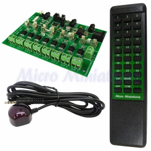
The standard MK-005 remote control dolls house and model scenery lighting controller including model railway layouts is supplied with 3 components. The Main Control Unit, this is the heart of the model remote control lighting system and is where all the electrical connections are made, the unit also has 11 LEDs to indicate the status of the dolls house and model lighting outputs, the indicators also display other programming parameters. The Remote Control Handset is used to program and control the Main Control Unit. The IR Sensor receives the signals from the handset and should be located in a suitable position in sight of the operator. Please read all instructions before making any connections to the MK-005 model remote control unit. Once the instructions have been read, we recommend that after plugging in the Remote Sensor (into socket 12 and connecting the power), that you familiarize yourself with the operation of the unit before connecting any of the outputs.
Main Control Unit
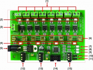
- Outputs 1 to 8
- Output status indicators
- Wire power connector
- Fuse blown indicators
- 2.1mm Standard power socket
- Fuses (3 Amp)
- System active indicator
- Program mode indicator
- Remote signal receive indicator
- Expansion board 2 jumper
- Expansion board 3 jumper
- Remote sensor socket
- Expansion board socket
- Reserved
- Program extension indicator socket
Connecting the power to your remote control model lighting controller
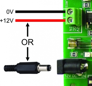
The MK-005 dolls house lighting controller operates from a 12V DC regulated power supply and must display the symbol shown below. The power may be connected to either the 2 pin screw terminal block 3 or directly from a standard 2.1mm DC plug 5.

Connecting the remote control sensor

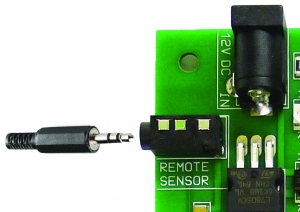
Ensure that the power to the MK-005 is switched off. Insert the Remote Sensor plug into the Remote Sensor socket 12.
Connecting multiple remote control lighting units together
Up to 3 MK-005 model lighting remote control units can be connected together and operated by the same remote handset. Expanding the number of individual outputs from 8 to 16 or 24. Plug connections are made using the cables supplied with additional expansion boards.
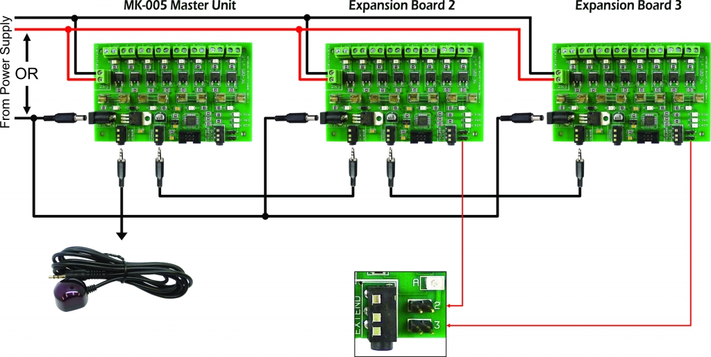
Note: Both power wiring methods are shown above. As mentioned earlier, only one method should be used. Do not make connections to both the 2.1mm power socket 5 and the 2 pin terminal block 3.
To configure the remote control model lighting expansion board, place the supplied jumper on jumper location 2 for board 2 or jumper location 3 for board 3. Master units do not require a jumper.
Connecting the Program Extension Indicator
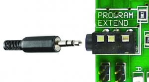
If you are using the optional Program Extension Indicator then ensure the power to the MK-005 remote control model lighting controller is switched off and insert the Extender plug into the Program Extend socket 15.
Connecting the outputs
Before connecting the outputs of the model remote control unit, we recommend that after connecting the remote sensor and the power, the unit is powered on. The System Active Indicator 7 should glow red. All other indicators should be off. At this point, we advise you to familiarise yourself with programming and operating the unit. The green Output Status Indicators 2 will reflect the status of each of the outputs. See the programming and operating section in the instructions. Ensure the power is turned off before making any connections. It is good practice to connect and test each output one at a time. Ensure the output functions okay before moving on to the next. Avoid short circuits at all costs. At best, a short circuit will cause the MK-005 to behave abnormally, at worst the unit could be damaged. If the output does not behave as expected then turn the power off straight away and find the short or open circuit. A multimeter will prove invaluable when trying to locate faults. The output connectors 1 are located at the top of the board and are labelled O/P 1 – 8. The terminals are designed to accept wire up to 2mm in diameter and the standard 1/12 scale scale plugs fitted to dolls house lights.
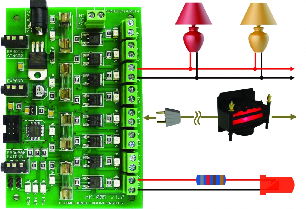
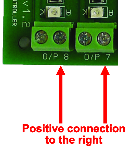
Shown here are some connection examples of various types of dolls house lighting and modeling applications. Non polarized components such as dolls house lights with conventional bulbs can have their wires connected to either terminal. Polarized items such as LEDs or additional electronic accessories which have a positive and negative must be connected the correct way round. The positive connection should be made to the right hand screw terminal as shown.
Important The MK-005 model remote control system outputs 12 volts DC. Lights, LEDs or other devices which do not operate on this voltage should not be connected directly to the outputs.
Programming the MK-005 Remote dolls house lighting and model railway lighting controller.
Overview
The MK-005 remote control model scenery and dolls house lighting controller is an extremely versatile and sophisticated lighting controller but exceptionally easy to operate using the remote control handset. The unit has 8 independent outputs which can be expanded up to 24 outputs by adding additional units. Each of the outputs can be programmed to behave differently with a choice of 5 different modes.
- Mode 1 Normal This mode is intended to operate LEDs or incandescent type dolls house or modelling bulbs. The brightness of the outputs can be varied from virtually off to fully on.
- Mode 2 Candle The Candle mode simulates a burning candle. The output can be programmed to be virtually static through to emulating a candle in a draughty hallway. This mode has 24 different settings.
- Mode 3 Fire Simulates a model coal or wood fire, the output can be programmed from glowing embers through to a raging fire. There are 8 different settings for the fire mode.
- Mode 4 Flash This mode flashes the output from a slow beat through to fast pulsing.
- Mode 5 Static Use the static mode to turn on and off other electronic equipment by remote control.
Each of the 8 (up to 24) outputs can be combined into a single Group. This feature allows you to turn on or off predefined sets of outputs with a couple of key presses. For instance, you may be using 4 of the outputs to control the lights on the top floor of your dolls house or area of scenery. These outputs can be combined into a Group and turned on or off altogether. You may have up to 10 independent Groups programmed with 1 to 24 outputs. Any Output can be included in as many Groups as you wish. See Setting Up a Group of Outputs.
Note, throughout these instructions the term Permanently Saved will be used. This means that the settings will be saved and remain stored after power off. The settings can be changed again in the future if required. It does not mean that the settings cannot be altered again. The blue Program Mode Indicator 8 will be referred to as PMI throughout these instructions.
Factory defaults
When you receive your MK-005 model railway remote control unit, it will be programmed with the following values:-
- All output modes are set to Normal mode.
- All outputs are set to maximum brightness.
- All outputs are turned off.
- All 10 groups of outputs are empty.
Restoring factory defaults on your dolls house remote control lighting system
Note, all current settings will be erased after performing a factory reset. To reset your MK-005 model lighting controller to it’s original settings, proceed as follows.
Step 1 Press and hold the Com key for approximately 1 second. All of the outputs will flash twice then go off. See note 5. The blue Program Mode Indicator (PMI) will turn on.
Step 2 Press and hold the Save key for approximately 2 seconds. The outputs will flash 8 times. See note 5. Factory Reset is now complete. The programming LED will turn off and the unit will revert to normal operation. All outputs will be off.
Changing an output operating mode
If you are intending to control anything other than a light bulb or LED (using Static mode) then do not connect the device to the output until after the output has been programmed. To observe the status of the output, connect a bulb or LED to the output or watch the corresponding output status indicator 2 on the MK-005 control unit. Once the output has been correctly programmed then the device may be connected. Note electronic devices should be controlled using Static mode.The device being controlled could be damaged if any other mode is used. To change the mode of an output, follow these steps:-
Step 1 All modes. Press and hold the number key corresponding to the output to modify. (1 to 24, see note 1) After approximately 1 second the output will flash twice and the blue PMI will turn on, see note 7. Release the output number key.
Step 2 All modes. Press the key corresponding to the mode required.
- Normal adjustable brightness
- Simulated candle
- Simulated fire
- Flashing output
- Static output
The output selected in step 1 will flash 3 times.
Step 3 Flash or Static modes If Flash or Static mode has been selected then:-
Press the Com key to use the selected mode, see note 2, the output will flash twice.
or
Press the Save key to permanently save the selected mode, see note 3, the output will flash 3 times.
Programming the Flash or Static mode is now complete the blue PMI will turn off, the output will be turned on and the MK-005 will return to normal operation.
Step 3 Normal, Candle or Fire Modes If Normal, Candle or Fire mode has been selected then:-
Press the Plus (+) key if the output is connected to a bulb. The output will flash 4 times.
or
Press the Minus(-) key if the output is connected to a LED. The output will flash 3 times.
Step 4 Normal, Candle or Fire Modes
Press the Com key to use the selected mode, see note 2, the output will flash twice.
or
Press the Save key to permanently save the selected mode, see note 3, the output will flash 3 times.
or
Press the Off key to abandon all changes. The output will flash once.
Programming the Normal, Candle or Fire modes is now complete the blue PMI will turn off, the output will be turned on and the MK-005 will return to normal operation.
Changing the output mode settings of your MK-005 model lighting controller.
Once an output for your dolls house or model scenery lighting has been programmed with a mode then additional settings such as brightness, fire intensity etc. can be adjusted. Note that the MK-005 only adjusts the setting associated with the programmed Mode of the Output. E.g. If an Output is programmed to simulate a fire (Mode 3) then the Fire Intensity is the only setting that can adjusted. The following explains how to adjust the settings of each mode.
Mode 1 Adjusting the brightness of the normal output mode.
Step 1 Press and release the Com key. The blue PMI will turn on, see note 7.
Step 2 Press the number key (1 to 24) corresponding to the Output to adjust. (The output must have been previously programmed in Mode 1). The Output will flash twice and then return to it’s previous brightness
Step 3 Set the brightness level by pressing any of the number keys between 1 to 24 (1 = dimmest, 24 = brightest). Use the Plus (+) and Minus (-) keys to finely adjust the brightness. See note 6.
Step 4 When the brightness is set press the Com key to use the setting, see note 2. The output will flash twice.
or
Press the Save key to permanently save the new brightness level. See Note 3. The Output will flash 3 times
Programming the brightness is now complete, the blue PMI will turn off and the MK-005 remote control dolls house lighting controller will return to normal operation.
Mode 2 Adjusting the flicker rate of a simulated dolls house candle or model railway lantern
Step 1 Press and release the Com key. The blue PMI will turn on, see note 7.
Step 2 Press the corresponding number key of the Output to adjust. (The output must have been previously programmed in Mode 2). The Output will flash twice and then return to it’s previous flicker rate.
Step 3 Use the number keys between 1 and 24 to set the required flicker rate. (1 = virtually still, 24 = in a draughty room). The output will change to reflect the new setting.
Step 4 When the desired flicker rate is set press the Com key to use the setting, see note 2. The output will flash twice.
or
Press the Save key to permanently save the new flicker rate. See note 3. The Output will flash 3 times
Programming the flicker rate is now complete, the blue PMI will turn off and the MK-005 remote control unit will return to normal operation.
Mode 3 Adjusting the intensity of a simulated model railway or dolls house fire.
Step 1 Press and release the Com key. The blue PMI will turn on, see note 7.
Step 2 Press the corresponding number key of the Output to adjust. (The output must have been previously programmed in Mode 3). The Output will flash twice and then return to it’s previous flicker rate
Step 3 Use the number keys between 1 and 8 to set the required fire intensity. (1 = glowing embers, 8 = roaring fire). The output will change to reflect the new setting.
Step 4 When the desired intensity is set press the Com key to use the setting, see note 2. The output will flash twice.
or
Press the Save key to permanently save the new flicker rate. See note 3. The Output will flash 3 times.
Programming the flicker rate is now complete, the blue PMI will turn off and the MK-005 model light remote controller will return to normal operation.
Mode 4 Adjusting the flash rate
Step 1 Press and release the Com key. The blue PMI will turn on, see note 7
Step 2 Press the corresponding number key of the Output to adjust. (The output must have been previously programmed in Mode 4). The Output will flash twice and then return to it’s previous flash rate.
Step 3 Set the flicker rate by pressing any of the number keys between 1 and 24 (1 = slowest, 24 = fastest). Use the Plus (+) and Minus (-) keys to finely adjust the flash rate. See note 6.
Step 4 When the desired intensity is set press the Com key to use the setting, see note 2. The output will flash twice.
or
Press the Save key to permanently save the new flash rate. See note 3. The Output will flash 3 times.
Programming the flash rate is now complete, the blue PMI will turn off and the MK-005 will return to normal operation.
Mode 5 Static Mode
The are no parameters to adjust in Static mode. The output will be either on or off.
Setting up a group of outputs
All outputs including outputs on additional expansion boards can be grouped together so that they may all be switched on or off at the same time. An example might be all of the lights and fireplaces on the ground floor. Up to 10 individual groups can be programmed. Group outputs are not restricted to one board, the outputs on additional expansion boards (outputs 9 – 16 and 17 – 24) can also be included. Any output can be included in as many groups as required. To setup a group, follow these steps:-
Step 1 Press and hold the Com key for approximately 1 second. All of the outputs will flash twice then go off. The blue PMI will turn on, see note 7.
Step 2 Press the key corresponding to the group to be programmed (Keys 1 to 10). All of the outputs will flash once
Step 3 Toggle all required outputs on or off by pressing the corresponding output key (1 to 24). See note 10.
Step 4 Press the Com key to use the settings but not permanently save them. The outputs will flash once. See note 5.
or
Press the Save key to permanently store the settings, see note 3. All the outputs will flash 3 times. See note 5.
Step 5 Return to step 2 and select another group to program
or
Press the Off key to exit. The Blue PMI will turn off and the MK-005 will return to normal operation.
Disabling indicator outputs
When programming the MK-005 dolls house lighting controller, the outputs will often flash to indicate the programming status. If the optional indicator expansion unit (OIEU) is plugged into the MK-005 then the outputs on that board will automatically be disabled from flashing. if additional boards have been added then the outputs on these boards may be manually disabled from flashing. To manually disable or enable flashing outputs, proceed as follows:-
Step 1 Press and hold the Com key for approximately 1 second. All of the outputs will flash twice and then go off. See note 5. The blue Program Mode Indicator (PMI) will turn on.
Step 2 To enable outputs to flash press the Plus (+) key. the outputs will flash twice, see note 5. The blue Program Mode Indicator will go out and the unit will revert to normal operation.
or
To disable flashing outputs press the Minus (-) key. The blue PMI will turn off and the MK-005 will revert to normal operation. If fitted then the white indicator on the OIEU will flash once.
Operating the MK-005 model remote control unit
Remote key functions
When the MK-005 is not in programming mode, the remote control keys are used to operate the outputs individually or as a group. The current settings can also be saved and the various programming modes entered.
Single key operations
1 to 24 Keys 1 to 24 toggle the corresponding output on or off. Press and release the key once to turn the output on, press and release the key again to turn the output off. (Keys 9 to 16 and 17 to 24 operate the outputs on expansion boards 2 and 3, these keys will be ignored if the expansion board is not present.
Off All of the outputs can be turned off by pressing and releasing the Off key.
On Pressing and releasing the On key will restore all of the outputs to their previous state prior to pressing the Off key. Pressing and holding the On key for approximately 1 second will turn all outputs on.
Save To store all of the current settings, press and hold the Save key for approximately 1 second. The outputs will flash 3 times to confirm, see note 5, release the Save key. All of the settings for all of the outputs including the on/off status will be stored.
Turning a group of outputs on (Models sold prior to 1st April 2020)
Once one or more of the 10 Groups have been programmed then the whole group of outputs can be switched on in a couple of key presses. To turn on a Group, proceed as follows:-
Step 1 Press and release the Plus (+) key. See note 7. All outputs will switch off and the blue PMI will turn on.
Step 2 Press the number key (1 to 10) corresponding to the Group required. The selected Group outputs will turn on as previously programmed. If this is not the required Group then select another Group by pressing another number key (1 to 10).
or
Press the Plus (+) or Minus (-) keys to rotate forwards or backwards through the 10 Groups in turn. See note 11.
Step 3 Press the Com key to use the current Group. The programming LED and all of the Outputs will flash once, See Note 5. The blue PMI will turn off and the unit will return to normal operation with the selected Group outputs turned on
or
Press the Off key to return to the previous output status. The blue PMI will turn off and the unit will return to normal operation.
Turning a group of outputs on (Models sold after 1st April 2020)
Once one or more of the 10 Groups have been programmed then the whole group of outputs can be switched on in a couple of key presses. To turn on a Group, proceed as follows:-
Step 1 Press and release the Plus (+) key. See note 7. The blue PMI will turn on.
Step 2 Press the number key (1 to 10) corresponding to the Group required. The selected Group outputs will turn on, the blue PMI will turn off and the unit will revert to normal operation.
or
Press the Off key to return to the previous output status. The blue PMI will turn off and the unit will return to normal operation.
Turning a group of outputs off (Models sold after 1st April 2020)
To turn off a Group of outputs, proceed as follows:-
Step 1 Press and release the Minus (-) key. See note 7. The blue PMI will turn on.
Step 2 Press the number key (1 to 10) corresponding to the Group required. The selected Group outputs will turn off, the blue PMI will turn off and the unit will revert to normal operation.
or
Press the Off key to return to the previous output status. The blue PMI will turn off and the unit will return to normal operation.
Notes
Note 1 Only 8 of the 24 number keys will operate the outputs, the valid key range will depend on whether the MK-005 is the Master Unit or Expansion Board 2 or Expansion Board 3.
- Master Unit Keys 1 to 8 are active and correspond to outputs 1 to 8
- Expansion Board 2 Keys 9 to 16 are active and correspond to outputs 1 to 8
- Expansion Board 3 Keys 17 to 24 are active and correspond to outputs 1 to 8
Note 2 All outputs will revert back to the last saved settings when the unit is powered off.
Note 3 All of the output settings will be retained after powering off the MK-005 but can be changed again in the future if required.
Note 4 Only the outputs which were on prior to the Off key being pressed will be switched back on. Outputs which have been switched on after pressing the Off key will remain on.
Note 5 Outputs programmed in Static mode will not flash, this is to avoid the risk of damaging electronic devices which may be connected. Also the outputs will not flash if the they have been manually disabled or the optional indicator expansion unit is connected, the white light on the optional indicator expansion unit will always flash if connected
Note 6 The setting may be adjusted by using either the number keys (1 to 24) or the Plus (+) and Minus (-) keys or a combination of the two. Pressing and holding either of the Plus (+) or Minus (-) keys will rapidly alter the setting. The output will adjust immediately to reflect the change.
Note 7 From this point onward, the programming mode can be cancelled by pressing the Off key. All settings will be restored to their previous values, the output will flash once and the blue PMI will turn off.
Note 8 The flash rate may be adjusted by using either the numeric keys 1 to 24 or the Plus (+) and Minus (-) keys or a combination of the two. Pressing and holding either of the Plus (+) or Minus (-) keys will rapidly alter the setting, however as this is a flashing mode, the output may not get time to reflect the change. It is recommended that the Plus (+) and Minus (-) keys are pressed and released rather than being held down.