The MK-003 Simple Wiring Connector provides an easy method of connecting up to 12 switchable outputs to one single power source. It is designed to operate on 12V DC. Individual outputs can be switched on and off and have an indicator to display the status. It is ideal for connecting and switching 12 volt dolls house lights and model scenery lights including model railway accessories.
Note that the green indicator LED is illuminated when the output is off. There is also a master ‘Power On’ indicator LED.
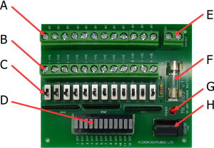
A) Output -Ve (0V) connections x 12
B) Output +Ve (+12V) connections x 12
C) Individual output ON OFF switches
D) Output ON OFF status indicators
E) Power terminal connector
F) Safety fuse (5 amps)
G) Power on indicator
H) Power 2.1mm socket
The output LED indicators (D) have a film strip to protect the LEDs during manufacture and transport. Gently peel back to remove the protective strip.
The MK-003 operates on 12V DC. Power can be connected to either the terminal strip power connector (E) or the 2.1mm power socket (H) via a standard 2.1mm male power plug with centre positive connection. Do not connect to both. Note the voltage polarity if wiring directly to the terminal connector (E). Positive should be connected to +12V and negative connected to 0V.
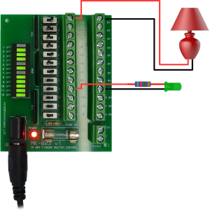
Connections are made via the 2 rows of output connectors (A & B). Each output pair is labelled 1 to 12 respectively. For conventional bulbs such as dolls house lights, the polarity is not important and the +Ve and 0V can be connected either way round. When connecting a polarity sensitive component such as an LED then the correct polarity should be observed.
Shown above are outputs 1 and 9 connected to a conventional 12 volt dolls house light and an LED respectively. The +Ve and 0V connections to the light are not important and could be connected either way. However the correct polarity should be observed when connecting to an LED
When making connections, ensure that the connector terminal screw is turned fully anti-clockwise before inserting the wire. Tighten the terminal by turning the screw fully clockwise. Do not over tighten.?Slide the output switches toward connector B to turn outputs on or toward the output status indicators to turn off. Note. The green LED indicators illuminate when the outputs are off.