It is not straight forward to display the status (position) of a point motor as the power to move the track segment is only applied for a fraction of a second, therefor the switch output cannot be used to power a LED or indicator bulb. The reason the power is only applied for a short period is that point motors will burn out quickly if they are subjected to more than a second or two of constant power. The simplest way to overcome this is to use momentary switches to apply a short pulse to the point motor. Momentary switches used are usually SPDT (single pull, double throw) with a centre off position. The switch will return to it’s centre position when released. This method and especially when used in conjunction with a CDU (Capacitor Discharge Unit) will protect the point motor from being damaged. However it cannot be used to display the points motor position as the power is only present for a fraction of a second. Take a look at our technical articles for more information on this subject.
Overcoming the problem of indicating the state of a set of points can be achieved in two ways. One way is to attach a switch to the points which moves with the point motor. Some point manufactures offer this option but it tends to be unreliable as the mechanical action does not always happen properly and quite often the switch fails to make contact. A far better solution is to use one (or more) of our PPI (Points Position Indicator) boards. These have an on board microprocessor which detects the tiny pulse sent to the point motor and lights it’s corresponding LED. This method never fails and is far more reliable as there is no mechanical action to rely on. It is oblivious to key bounce and multiple pushes of the switch. The points position indicator remembers the state of the points when the power is removed so when power is restored the LEDs are returned to their original state. Our PPI board will detect DC or AC input pulses from 5v to 30v
Our PPI boards are available with 3 different LED options
- Standard LEDs:- Supplied with 8 red and 8 green standard LEDs and 16 resistors
- Pre-Wired LEDs:- Supplied with 8 Red and 8 Green pre-wired LEDs
- Bi-Coloured LEDs:- Supplied with 8 Red/Green LEDs and 8 resistors
Shown below are the LED connections to our points position indicator. Only outputs 1 and 2 are illustrated, outputs 3 to 8 are connected in the same way. Note, more than 1 led can be connected to each output allowing signals to be added at different points of the track and also to mimic boards. The Output LED +Ve connections are show in Red. Note that these are shown connected into just one of the two terminals, however both or either can be used. Individual connections are show in Black.
Connecting Standard LEDs
The shorter LED lead (shown in Black) should be connected to one end of a resistor. The other end of the resistor is connected into either the A or B output terminal. The long leads (shown in Red) are connected together into one or both of the Output LED +Ve terminals.
Connecting Pre-Wired LEDs
The Red LED wires should all be connected into either of the Output LED +Ve terminals. The Black wires are connected into the individual A or B output terminals.
Connecting Bi-Coloured LEDs
The centre pin (longest lead) shown in Red should be connected to one end of a resistor. The other end of the resistor is connected into either of the Output LED +Ve terminals. The shortest lead (LED glows Green) is connected to either the A or B output terminal. Connect the middle length lead (LED glows Red) into the remaining A or B terminal. Note The bi-coloured LEDs supplied with this unit are Common Anode.
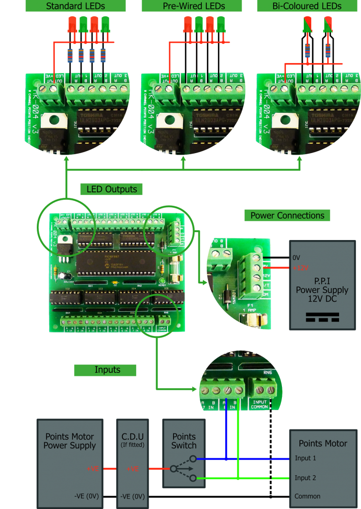
Connecting the Power
The Points Position Indicator board operates from 12V DC with at least 1 Amp capacity. The unit may not operate correctly with any other power supply. Ensure that the power supply used has the marking shown below. Connect the power supply 0V and +12V to the 0V and +12V terminals on the PPI board as shown.
![]() For correct operation this symbol must be displayed on the PPI Power Supply label.
For correct operation this symbol must be displayed on the PPI Power Supply label.
Connecting the Input Signals
The connections for input 8 on the P.P.I board are shown to the left. The remainder of inputs should be wired the same. However (assuming only one CDU and Points Motor Power Supply are used for all 8 inputs) then only 1 of the -VE (0V) wires (shown dotted) needs to be connected to the PPI Input Common.
Common Problems
Q Points Position Indicator Power LED doesn’t illuminate
A Check the power supply and the fuse. Only use a 1A Fast Blow Fuse as a replacement.
Q All PPI LEDs including the power LED are flashing
A The PPI power supply is not suitable. Use a different power supply.
Q The points operate okay but the PPI LEDs are not changing
A The switching connections are back to front or the Input Common is not connected correctly. Refer to the Inputs section and ensure that the +VE and -VE are correctly wired through
Important
The screw terminals used on this unit are an efficient modern type which clamp upwards. Ensure that the screw are fully open (turned anti-clockwise) before inserting the wire.
Do not use an AC power supply to power the PPI. This could damage the unit.
Avoid shorting any of the outputs. Make connections to the PPI with the power off.
Full technical support is available if required